The architecture of 8085 consist of various components like:
- Accumulator & Register sets.
- Program counter and stack pointer.
- Flag Register.
- ALU.
- Instruction decoder and machine cycle encoder.
- Address buffer.
- Address/data buffer.
- Increment/Decrement latch.
- Interrupt control.
- Serial I/O like SOD,SID.
- Timing and Control circuit.

Accumulator:
- The accumulator is an 8-bit register then is part of the arithmetic/logic unit(ALU).
- This register is used to store 8-bit data this data is used to perform arithmetic & logical operation.
- The result of an operation is stored in the accumulator.
- The accumulator is also identified as register A.
- The accumulator is used for data transfer between an I/O port and memory location.
Register sets:
- The 8085 simulator has six general-purpose registers to store 8-bit data; these are identified as B, C, D, E, H and L. They can be combined as register pair likeBC, DE and HL – to perform some 16-bit operations.
- The programmer can use these registers to store or copy data into the registers by using data copy instructions.
- Out of these six registers, four 8-bit registers are scratch pad registers which are accessible to the programmer and hence can be used to temporarily store data during a program execution.
- And the two registers H and L are utilized in indirect addressing mode. In this mode, the memory location i.e. the address is specified by the contents of the registers.
Program Counter (PC):
- 16 bit register which holds the memory address of the next instruction to be executed in the next step.
- This 16-bit register deals with sequencing the execution of instructions. This register is a memory pointer. Memory locations have 16-bit addresses, and that is why this is a 16-bit register.
- The microprocessor uses this register to sequence the execution of the instructions. The function of the program counter is to point to the memory address from which the next instruction is to be fetched. When a byte (machine code) is being fetched, the program counter is incremented by one to point to the next memory location.
Stack Pointer (SP):
- Stack pointer is used during subroutine calling and execution.
- The stack pointer is also a 16-bit register used as a memory pointer. It points to a memory location in R/W memory, called the stack.
Flag or status register:
- The ALU includes five flip-flops, which are set or reset after an operation according to data conditions of the result in the accumulator and other registers. They are called Zero(Z), Carry (CY), Sign (S), Parity (P), and Auxiliary Carry (AC) flags.
- The most commonly used flags are Zero, Carry, and Sign. The microprocessor uses these flags to test data conditions.
- For example, after an addition of two numbers, if the sum in the accumulator is larger than eight bits, the flip-flop uses to indicate a carry -- called the Carry flag (CY) -- is set to one.
- When an arithmetic operation results is zero, the flip-flop called the Zero(Z) flag is set to one.
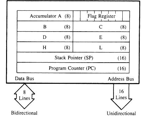
- The Figure shows an 8-bit register, called the flag register, adjacent to the accumulator..

Flag is an 8-bit register containing 5no.s of 1-bit flags:
- Sign - If the result of the latest arithmetic operation is having MSB (most- significant bit) „1‟ (meaning it is a negative number), then the sign flag is set. Otherwise, it is reset to „0‟ which means it is a positive number.
- Zero - If the result of the latest operation is zero, then zero flag will be set; otherwise it be reset.
- Auxiliary carry - set if there was a carry out from bit 3 to bit 4 of the result.
- Parity - set if the parity (the number of set bits in the result) is even. i.e., If the result of the latest operation is having even number of „1‟s, then this flag will be set. Otherwise this will be reset to „0‟. This is used for error checking.
- Carry - set if there was a carry during addition, or borrow during subtraction/comparison. Otherwise it will be reset.
Instruction register or Decoder
- Instruction register holds the instruction that is currently being processed.
- Once the instruction is fetch from the memory, it is reloaded in the instruction register for some time, after the decoder decode the instruction performing some event or task.
Address buffer:
- The remaining higher order address lines form the address buffer ranging from[A15-A8].This is having the unidirectional buffer
Address/data buffer:
- The address bus will be having 16 address lines[A15-A0] .In which A7-A0 are called as lower addressing lines and these are multiplexed with data lines[D7-D0] to form multiplexed address /data buffer .The address/data buffer is the bidirectional bus.
Increment/Decrement Address Latch:
It increments/ decrements the address before sent to the address buffer
Interrupts:
The processor has 5 interrupts. They are presented below in the order of their priority (from lowest to highest):
- INTR is maskable 8080A compatible interrupt. When the interrupt occurs, the processor fetches from the bus one instruction, usually one of these instructions: One of the 8 RST instructions (RST0 - RST7). The processor saves current program counter into stack and branches to memory location N * 8 (where N is a 3- bit number from 0 to 7 supplied with the RST instruction).
- CALL instruction (3 byte instruction). The processor calls the subroutine, address of which is specified in the second and third bytes of the instruction.
- RST5.5 is a maskable interrupt. When this interrupt is received the processor saves the contents of the PC register into stack and branches to 2CH (hexadecimal) address.
- RST6.5 is a maskable interrupt. When this interrupt is received the processor saves the contents of the PC register into stack and branches to 34H (hexadecimal) address.
- RST7.5 is a maskable interrupt. When this interrupt is received the processor saves the contents of the PC register into stack and branches to 3CH (hexadecimal) address.
- TRAP is a non-maskable interrupt. When this interrupt is received the processor saves the contents of the PC register into stack and branches to 24H (hexadecimal) address.
All maskable interrupts can be enabled or disabled using EI and DI instructions
Serial I/O Control
There are control signals used for controlling 8085 these are subdivided into 2 types:
- SID(serial input data): This is used for transferring of data into the memory serially.
- SOD(serial output data): This is used for transferring of data from memory to external devices
Interrupt control is used to transfer the ISR to the CPU.