Developing a conceptual scheme or model is the first step of a database design. The goal is to adequately capture the specifications of the data and constraints to be represented in the database.
To do so, the database designer and the end user should closely collaborate. The main focus is to capture the semantics of the business process as accurately as possible without being concerned about DBMS-related issues.
This purpose requires a high-level model, such as the (E)ER model. This allows the database designer to capture data requirement end provide a user-friendly representation to the end user so that he or she can also accurately understand what has been modeled. If the model is agreed by both parties, we can proceed to the database design.
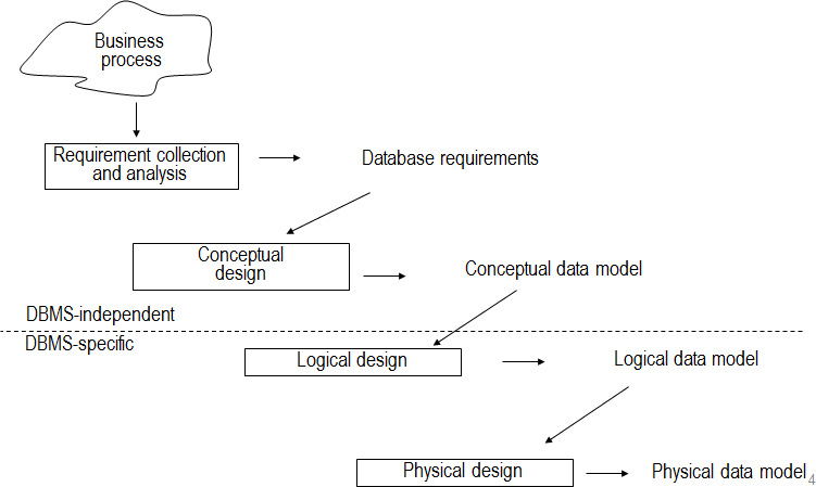
These are the various steps of the database design. We start from a business process and think about the procurement application, invoice handling process, salary administration or logistics process. Database designer and end user will closeley collaborate to write down the data requirements of the process in a conceptual data model. During thhis step, the database designers interview prospective database users to understand and document their data requirements. The result of this step is a concesely written set of users’r requirements. As mentioned before, there should be a high-level model that is easy to understand from the business user and fromal enough to the database designer. This conceptual model will have its limitations …
Once the requirements have been collected and analyzed, the next step is to create a conceptual schema for the database, using a high-level conceptual data model. This is the so called conceptual design.
Once all parties have agreed, it can be mapped to a logical data model which take into account the implementation environment. That is to say that the logical data model is the data model that will be used by the DBMS for actual implementation.
In a final step, the logical data model can be mapped to a physical data model. During this mapping process, semantics could get lost or added. During this desing, the internal storage strucutres, file organisations, indexes, access paths, … are sepcified. In a parallel with these activities, application programs are designed and implemented as database transactions corresponding to heigh-level transaction specifications.
Hierarchical Model
The hierarchical model is one of the first data models that was developed. It was developed during the Apollo project. It is purely based on a hierarchical data model. No formal description is available and it has several structural limitations and is considered to be legacy.
The two key building blocks are:
A record type is a set of records describing a set of similar entities. Ex: a product record type or a supplier record type. It has 0, 1 or more records. It consists out of data fields or data items. Ex: a product record type has a field product name, product number, product color, etc.
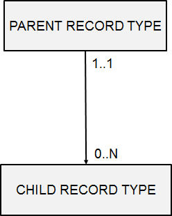
Relational type connects two records type. It models the relationships between records type. Only 1 to n relationship types can be modeled. Hence, a parent record type can have multiple child record types. But a child record type has at most one parent record type. Relationship types can be nested. Hence the child record type can be parent in another relationship type, which allows building hierarchical structures. The root record type is the one the sits at the top of the hierarchy. A leaf-record type sits at the bottom of the hierarchy.
We have a parent and a child record type. The parent record can be connected to minimum zero max N child records whereas the child can only be connected to minimum one or maximum one parent record type. Hence, the child record is always connected to exactly one parent. No other cardinalities are supported in the hierarchical models. Therefore, it makes it very restrictive in terms of expressive power. The relationship type is always summarized in terms of the maximum cardinalities. Here we can say the hierarchical model only supports 1 to N relationship types.
In this model, all record data needs to be retrieved by navigating from the root node of the hierarchical structure. In other words, the DML adopted is procedural, which is not so nice. It is also limited in terms of expressive power.
Besides, there is no straightforward way to model N:M and 1:1 relationship types. To implement a N:M relationship type, we can assign one record type as the parent and the other as the child record type. We transform the network structure to the three-structure. Every relationship attribute can be put in a child record type. But this solution will create redundancies.
Another alternative is to create two hierarchical structures and connect them using a virtual child- record type and a virtual parent/child relationship type. Pointers can then be used to navigate between both structures. The relationship type attributes can be put into a virtual child record type. This solution has no more redundancies since multiple virtual Childs can refer to one virtual parent. This structure has no more redundancies, it’s clear but not so nice to maintain.
1:1 relationship types are a special case of a 1 to N relationship type with N = 1. This relationship cannot be supported in the hierarchical model. The application programs should take care of this !
The hierarchical models only allow relationships types of degree 2, in other words, with two participating record types. Recursive relationship types, with degree 1, need to be implemented using virtual child record types. The maximum and minimal cardinality is one. A child cannot be disconnected from its parents. This implies that once a parent record is removed then all connected child records will be removed as well.