Microoperations
- A computer executes a program consisting Each instruction is made up of shorter sub-cycles as fetch, indirect, execute cycle, interrupt.
- Performance of each cycle has a number of shorter operations called micro-operations.
- Called so because each step is very simple and does very little.
- Thus micro-operations are functional atomic operation of CPU.
- Hence events of any instruction cycle can be described as a sequence of micro-operations

Fig 3-7: Constituent Elements of Program Execution
Steps leading to characterization of CU
- Define basic elements of processor
- Describe micro-operations processor performs
- Determine functions control unit must perform
Types of Micro-operation
- Transfer data between registers
- Transfer data from register to external interface
- Transfer data from external interface to register
- Perform arithmetic/logical ops with register for i/p, o/p
Functions of Control Unit
- Sequencing
- Causing the CPU to step through a series of micro-operations
- Execution
- Causing the performance of each micro-op
These are done using Control Signals

Fig 3-8: Control Unit Layout
Inputs to Control Unit
- Clock
- CU causes one micro-instruction (or set of parallel micro-instructions) per clock cycle
- Instruction register
- Op-code for current instruction determines which micro-instructions are performed
- Flags
- State of CPU
- Results of previous operations
- From control bus
- Interrupts
- Acknowledgements
CU Outputs (Control Signals)
- Within CPU(two types)
- Cause data movement
- Activate specific ALU functions
- Via control bus(two types)
- To memory
- To I/O modules
- Types of Control Signals
- Those that activate an ALU
- Those that activate a data path
- Those that are signal on external system bus or other external interface.
- All these are applied as binary i/p to individual logic gates
Hardwired Implementation
- In this implementation, CU is essentially a combinational Its i/p signals are transformed into set of o/p logic signal which are control signals.
- Control unit inputs
- Flags and control bus
- Each bit means something
- Instruction register
- Op-code causes different control signals for each different instruction
- Unique logic for each op-code
- Decoder takes encoded input and produces single output
- Each decoder i/p will activate a single unique o/p
- Clock
- Repetitive sequence of pulses
- Useful for measuring duration of micro-ops
- Must be long enough to allow signal propagation along data paths and through processor circuitry
- Different control signals at different times within instruction cycle
- Need a counter as i/p to control unit with different control signals being used for t1, t2 etc.
- At end of instruction cycle, counter is re-initialised

Fig 3-9: Control Unit With Decoded Input
Implementation
- For each control signal, a Boolean expression of that signal as a function of the inputs is derived
- With that the combinatorial circuit is realized as control unit.
Problems With Hard Wired Designs
- Complex sequencing & micro-operation logic
- Difficult to design and test
- Inflexible design
- Difficult to add new instructions
Micro-programmed Implementation
- An alternative to hardwired CU
- Common in contemporary CISC processors
- Use sequences of instructions to perform control operations performed by micro operations called micro-programming or firmware
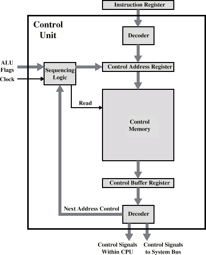
Fig 3-10: Microprogrammed Control Unit
- Set of microinsrurctions are stored in control memory
- Control address register contains the address of the next microinstruction to be read
- As it is read, it is transferred to control buffer register.
- For horizontal micro instructions, reading a microinstruction is same as executing it.
- Sequencing unit loads the control address register and issues a read command
CU functions as follows to execute an instruction:
- Sequencing logic issues read command to control memory
- Word whose address is in control address register is read into control buffer register.
- Content of control buffer register generates control signals and next address instruction for the sequencing logic unit.
- Sequencing logic unit loads new address into control address register depending upon the value of ALU flags, control buffer register.
- One of following decision is made:
- add 1 to control address register
- load address from address field of control buffer register
- load the control address register based on opcode in IR
- Upper decoder translates the opcode of IR into control memory address
- Lower decoder used for veritcal micro instructions.
Micro-instruction Types
- Each micro-instruction specifies single or few micro-operations to be performed - vertical micro-programming.
- Each micro-instruction specifies many different micro-operations to be performed in parallel - horizontal micro-programming
Horizontal Micro-programming
- Wide memory word
- High degree of parallel operations possible
- Little encoding of control information

Vertical Micro-programming
- Width is narrow
- n control signals encoded into log2 n bits
- Limited ability to express parallelism
- Considerable encoding of control information requires external memory word decoder to identify the exact control line being manipulated
