Processor Organization
- Things a CPU must do:
- Fetch Instructions
- Interpret Instructions
- Fetch Data
- Process Data
- Write Data

Fig: The CPU with the System Bus
- A small amount of internal memory, called the registers, is needed by the CPU to fulfill these requirements

Fig: Internal Structure of the CPU
- Components of the CPU
- Arithmetic and Logic Unit (ALU): does the actual computation or processing of data
- Control Unit (CU): controls the movement of data and instructions into and out of the CPU and controls the operation of the ALU.
Register Organization
- Registers are at top of the memory They serve two functions:
- User-Visible Registers - enable the machine- or assembly-language programmer to minimize main-memory references by optimizing use of registers
- Control and Status Registers - used by the control unit to control the operation
of the CPU and by privileged, OS programs to control the execution of programs
User-Visible Registers
Categories of Use
- General Purpose registers - for variety of functions
- Data registers - hold data
- Address registers - hold address information
- Segment pointers - hold base address of the segment in use
- Index registers - used for indexed addressing and may be auto indexed
- Stack Pointer - a dedicated register that points to top of a Push, pop, and other stack instructions need not contain an explicit stack operand.
- Condition Codes (flags)
Design Issues
- Completely general-purpose registers or specialized use?
- Specialized registers save bits in instructions because their use can be implicit
- General-purpose registers are more flexible
- Trend is toward use of specialized registers
- Number of registers provided?
- More registers require more operand specifier bits in instructions
- 8 to 32 registers appears optimum (RISC systems use hundreds, but are a completely different approach)
- Register Length?
- Address registers must be long enough to hold the largest address
- Data registers should be able to hold values of most data types
- Some machines allow two contiguous registers for double-length values
- Automatic or manual save of condition codes?
- Condition restore is usually automatic upon call return
- Saving condition code registers may be automatic upon call instruction, or may be manual
Control and Status Registers
- Essential to instruction execution
- Program Counter (PC)
- Instruction Register (IR)
- Memory Address Register (MAR) - usually connected directly to address lines of bus
- Memory Buffer Register (MBR) - usually connected directly to data lines of bus
- Program Status Word (PSW) - also essential, common fields or flags contained include:
- Sign - sign bit of last arithmetic operation
- Zero - set when result of last arithmetic operation is 0
- Carry - set if last op resulted in a carry into or borrow out of a high-order bit
- Equal - set if a logical compare result is equality
- Overflow - set when last arithmetic operation caused overflow
- Interrupt Enable/Disable - used to enable or disable interrupts
- Supervisor - indicates if privileged ops can be used
- Other optional registers
- Pointer to a block of memory containing additional status info (like process control blocks)
- An interrupt vector
- A system stack pointer
- A page table pointer
- I/O registers
- Design issues
- Operating system support in CPU
- How to divide allocation of control information between CPU registers and first part of main memory (usual tradeoffs apply)

Fig: Example Microprocessor Register Organization
The Instruction Cycle
Basic instruction cycle contains the following sub-cycles.
- Fetch - read next instruction from memory into CPU
- Execute - Interpret the opcode and perform the indicated operation
- Interrupt - if interrupts are enabled and one has occurred, save the current process state and service the interrupt
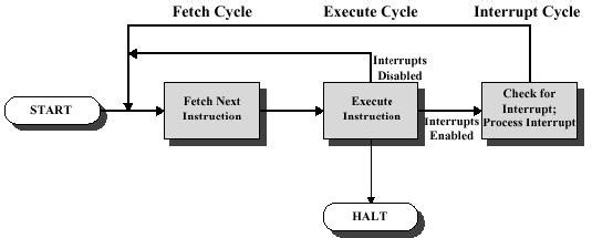
Fig: Instruction Cycles

Fig: Instruction Cycle State Diagram
The Indirect Cycle
- Think of as another instruction sub-cycle
- May require just another fetch (based upon last fetch)
- Might also require arithmetic, like indexing

Fig: Instruction Cycle with Indirect
Data Flow
- Exact sequence depends on CPU design
- We can indicate sequence in general terms, assuming CPU employs:
- a memory address register (MAR)
- a memory buffer register (MBR)
- a program counter (PC)
- an instruction register (IR)
Fetch cycle data flow
- PC contains address of next instruction to be fetched
- This address is moved to MAR and placed on address bus
- Control unit requests a memory read
- Result is
- placed on data bus
- result copied to MBR
- then moved to IR
Meanwhile, PC is incremented

Fig: Data flow, Fetch Cycle t1: MAR ß (PC)
t2: MBR ß Memory PC ß PC + 1
t3: IR(Address) ß (MBR(Address))
Indirect cycle data flow
- Decodes the instruction
- After fetch, control unit examines IR to see if indirect addressing is being If so:
- Rightmost n bits of MBR (the memory reference) are transferred to MAR
- Control unit requests a memory read, to get the desired operand address into the MBR
t1: MAR ß (IR(Address)) t2: MBR ß Memory
t3: IR(Address) ß (MBR(Address))

Fig: Data Flow, Indirect Cycle
Execute cycle data flow
- Not simple and predictable, like other cycles
- Takes many forms, since form depends on which of the various machine instructions is in the IR
- May involve
- transferring data among registers
- read or write from memory or I/O
- invocation of the ALU For example: ADD R1, X
t1: MAR ß (IR(Address)) t2: MBR ß Memory
t3: R1 ß (R1) + (MBR)
Interrupt cycle data flow
- Current contents of PC must be saved (for resume after interrupt), so PC is transferred to MBR to be written to memory
- Save location’s address (such as a stack ptr) is loaded into MAR from the control unit
- PC is loaded with address of interrupt routine (so next instruction cycle will begin by fetching appropriate instruction)
t1: MBR ß (PC)
t2: MAR ß save_address PC ß Routine_address
t3: Memory ß (MBR)

Fig: Data Flow, Interrupt Cycle