Each computer in a TCP/IP network must be given a unique identifier, or IP address. This address, which operates at Layer 3, allows one computer to locate another computer on a network. All computers also have a unique physical address, which is known as a MAC address. These are assigned by the manufacturer of the NIC. MAC addresses operate at Layer 2 of the OSI model.
An IP address (IPv4) is a 32-bit sequence of ones and zeros. To make the IP address easier to work with, it is usually written as four decimal numbers separated by periods. For example, an IP address of one computer is 192.168.1.2. Another computer might have the address 128.10.2.1. This is called the dotted decimal format. Each part of the address is called an octet because it is made up of eight binary digits. For example, the IP address 192.168.1.8 would be 11000000.10101000.00000001.00001000 in binary notation. The dotted decimal notation is an easier method to understand than the binary ones and zeros method. This dotted decimal notation also prevents a large number of transposition errors that would result if only the binary numbers were used.
Ipv4 Header:
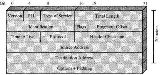
Fig: IPV4 Header
- Version ( 4 bits): Indicates the version number, to allow evolution of the protocol.
- Internet Header Length (IHL 4 bits): Length of header in 32 bit The minimum value is five for a minimum header length of 20 octets.
- Type-of-Service: The Type-of-Service field contains an 8-bit binary value that is used to determine the priority of each packet. This value enables a Quality-of-Service (QoS) mechanism to be applied to high priority packets, such as those carrying telephony voice data. The router processing the packets can be configured to decide which packet it is to forward first base on the Type-of-Service value.
- Total length: Total datagram length, in octets.
- Identifier (16 bits): A sequence number that, together with the source address, destination address, and user protocol, is intended to uniquely identify a datagram. Thus, the identifier should be unique for the datagram's source address, destination address, and user protocol for the time during which the datagram will remain in the internet.
- Fragment Offset: A router may have to fragment a packet when forwarding it from one medium to another medium that has a smaller MTU. When fragmentation occurs, the IPv4 packet uses the Fragment Offset field and the MF flag in the IP header to reconstruct the packet when it arrives at the destination host. The fragment offset field identifies the order in which to place the packet fragment in the reconstruction.
- Flags(3 bits): Only two of the bits are currently defined: MF(More Fragments) and DF(Don't Fragment):
- More Fragments flag (MF): The More Fragments (MF) flag is a single bit in the Flag field used with the Fragment Offset for the fragmentation and reconstruction of The More Fragments flag bit is set; it means that it is not the last fragment of a packet. When a receiving host sees a packet arrive with the MF = 1, it examines the Fragment Offset to see where this fragment is to be placed in the reconstructed packet. When a receiving host receives a frame with the MF = 0 and a non-zero value in the Fragment offset, it places that fragment as the last part of the reconstructed packet. An unfragmented packet has all zero fragmentation information (MF=0, fragment offset =0).
- Don't Fragment flag (DF): The Don't Fragment (DF) flag is a single bit in the Flag field that indicates that fragmentation of the packet is not If the Don't Fragment flag bit is set, then fragmentation of this packet is NOT permitted. If a router needs to fragment a packet to allow it to be passed downward to the Data Link layer but the DF bit is set to 1, then the router will discard this packet.
- IP Destination Address: The IP Destination Address field contains a 32-bit binary value that represents the packet destination Network layer host address.
- IP Source Address: The IP Source Address field contains a 32-bit binary value that represents the packet source Network layer host address.
- Time-to-Live: The Time-to-Live (TTL) is an 8-bit binary value that indicates the remaining "life" of the packet. The TTL value is decreased by at least one each time the packet is processed by a router (that is, each hop). When the value becomes zero, the router discards or drops the packet and it is removed from the network data flow. This mechanism prevents packets that cannot reach their destination from being forwarded indefinitely between routers in a routing If routing loops were permitted to continue, the network would become congested with data packets that will never reach their destination. Decrementing the TTL value at each hop ensures that it eventually becomes zero and that the packet with the expired TTL field will be dropped.
- Protocol: This 8-bit binary value indicates the data payload type that the packet is The Protocol field enables the Network layer to pass the data to the appropriate upper-layer protocol.
Example values are:
01 ICMP
06 TCP
17 UDP
- Header checksum (16 bits): An error-detecting code applied to the header only. Because some header fields may change during transit (e.g., time to live, segmentation-related fields), this is reverified and recomputed at each router. The checksum field is the 16-bit one's complement addition of all 16-bit words in the For purposes of computation, the checksum field is itself initialized to a value of zero.
- Options (variable): Encodes the options requested by the sending user.
- Padding (variable): Used to ensure that the datagram header is a multiple of 32 bits.
- Data (variable): The data field must be an integer multiple of 8 bits. The maximum length of the datagram (data field plus header) is 65,535 octets.