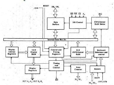
A programmable keyboard and display interfacing chip.Scans and encodes up to a 64-key keyboard. Controls up to a 16-digit numerical display.The Keyboard section has a built-in FIFO 8-character buffer. The display is controlled from an internal 16x8 RAM that stores the coded display information.
A0: Selects data (0) or control/status (1) for reads and writes between micro and 8279.
- BD: Output that blanks the displays.
- CLK: Used internally for timing. Max is 3 MHz.
- CN/ST: Control/strobe, connected to the control key on the keyboard
- CS: Chip select that enables programming, reading the keyboard, etc.
- DB7-DB0: Consists of bidirectional pins that connect to data bus on micro.
- IRQ: Interrupt request, becomes 1 when a key is pressed, data is available.
- OUT A3-A0/B3-B0: Outputs that send data to the most significant/least significant nibble of the display.
- RD(WR): Connects to micro's IORC or RD signal, reads data/status registers.
- RESET: Connects to system RESET.
- RL7-RL0: Return lines are inputs used to sense key depression in the keyboard matrix.
- Shift: Shift connects to the Shift key on the keyboard
The display section has eight output lines divided into two groups A0-A3 and B0-B3.
- The output lines can be used either as a single group of eight lines or as two groups of four lines, in conjunction with the scan lines for a multiplexed display.
- The output lines are connected to the anodes through driver transistor in case of common cathode 7-segment LEDs.
- The cathodes are connected to scan lines through driver transistors.
- The display can be blanked by BD (low) line.
- The display section consists of 16 x 8 display RAM. The CPU can read from or write into any location of the display RAM.
Scan section:
- The scan section has a scan counter and four scan lines, SL0 to SL3.
- In decoded scan mode, the output of scan lines will be similar to a 2-to-4 decoder.
- In encoded scan mode, the output of scan lines will be binary count, and so an external decoder should be used to convert the binary count to decoded output.
- The scan lines are common for keyboard and display.
- The scan lines are used to form the rows of a matrix keyboard and also connected to digit drivers of a multiplexed display, to turn ON/OFF.
CPU interface section:
- The CPU interface section takes care of data transfer between 8279 and the processor.
- This section has eight bidirectional data lines DB0 to DB7 for data transfer between 8279 and CPU.
- It requires two internal address A =0 for selecting data buffer and A = 1 for selecting control register of8279.
- The control signals WR (low), RD (low), CS (low) and A0 are used for read/write to 8279.
- It has an interrupt request line IRQ, for interrupt driven data transfer with processor.
- The 8279 require an internal clock frequency of 100 kHz. This can be obtained by dividing the input clock by an internal prescaler.
- The RESET signal sets the 8279 in 16-character display with two -key lockout keyboard modes.