Discuss about the mechanics of filtering in spatial domain. Mention the points to be considered in implementation neighbourhood operations for spatial filtering.
Some neighborhood operations work with the values of the image pixels in the neighborhood and the corresponding values of a subimage that has the same dimensions as the neighborhood.The subimage is called a filter,mask, kernel, template, or window,with the first three terms being the most prevalent terminology.The values in a filter subimage are referred to as coefficients, rather than pixels. The concept of filtering has its roots in the use of the Fourier transform for signal processing in the so-called frequency domain. We use the term spatial filtering to differentiate this type of process from the more traditional frequency domain filtering.
The mechanics of spatial filtering are illustrated in Fig.9.1. The process consists simply of moving the filter mask from point to point in an image. At each point (x, y), the response of the filter at that point is calculated using a predefined relationship. The response is given by a sum of products of the filter coefficients and the corresponding image pixels in the area spanned by the filter mask. For the 3 x 3 mask shown in Fig. 9.1, the result (or response), R, of linear filtering with the filter mask at a point (x, y) in the image is

which we see is the sum of products of the mask coefficients with the corresponding pixels
directly under the mask. Note in particular that the coefficient w(0, 0) coincides with image
value f(x, y), indicating that the mask is centered at (x, y) when the computation of the sum of products takes place. For a mask of size m x n,we assume that m=2a+1 and n=2b+1,where a and b are nonnegative integers

Fig.9.1 The mechanics of spatial filtering. The magnified drawing shows a 3X3 mask and the image section directly under it; the image section is shown displaced out from under the mask for ease of readability.
In general, linear filtering of an image f of size M x N with a filter mask of size m x n is given by the expression:

where, from the previous paragraph, a=(m-1)/2 and b=(n-1)/2. To generate a complete filtered image this equation must be applied for x=0,1,2,……, M-1 and y=0,1,2,……, N-1. In this way, we are assured that the mask processes all pixels in the image. It is easily verified when m=n=3 that this expression reduces to the example given in the previous paragraph.
The process of linear filtering is similar to a frequency domain concept called convolution. For this reason, linear spatial filtering often is referred to as ―convolving a mask with an image.‖ Similarly, filter masks are sometimes called convolution masks. The term convolution kernel also is in common use. When interest lies on the response, R, of an m x n mask at any point (x,y), and not on the mechanics of implementing mask convolution, it is common practice to simplify the notation by using the following expression:
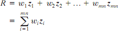
where the w’s are mask coefficients, the z’s are the values of the image graylevels corresponding to those coefficients, and mn is the total number of coefficients in the mask. For the 3 x 3 general mask shown in Fig.9.2 the response at any point (x, y) in the image is given by


Fig.9.2 Another representation of a general 3 x 3 spatial filter mask.
An important consideration in implementing neighborhood operations for spatial filtering is the issue of what happens when the center of the filter approaches the border of the image.Consider for simplicity a square mask of size n x n.At least one edge of such a mask will coincide with the border of the image when the center of the mask is at a distance of (n-1)/2 pixels away from the border of the image. If the center of the mask moves any closer to the border, one or more rows or columns of the mask will be located outside the image plane.There are several ways to handle this situation.The simplest is to limit the excursions of the center of the mask to be at a distance no less than (n-1)/2 pixels from the border. The resulting filtered image will be smaller than the original, but all the pixels in the filtered imaged will have been processed with the full mask. If the result is required to be the same size as the original, then the approach typically employed is to filter all pixels only with the section of the mask that is fully contained in the image.With this approach, there will be bands of pixels near the border that will have been processed with a partial filter mask.Other approaches include ―padding‖ the image by adding rows and columns of 0’s (or other constant gray level), or padding by replicating rows or columns.The padding is then stripped off at the end of the process.
This keeps the size of the filtered image the same as the original, but the values of the padding will have an effect near the edges that becomes more prevalent as the size of the mask increases.The only way to obtain a perfectly filtered result is to accept a somewhat smaller filtered image by limiting the excursions of the center of the filter mask to a distance no less than (n-1)/2 pixels from the border of the original image.