Explain about region based segmentation.
Region-Based Segmentation:
The objective of segmentation is to partition an image into regions. We approached this problem by finding boundaries between regions based on discontinuities in gray levels, whereas segmentation was accomplished via thresholds based on the distribution of pixel properties, such as gray-level values or color.
Basic Formulation:
Let R represent the entire image region. We may view segmentation as a process that partitions
R into n subregions, R1, R2..., Rn, such that
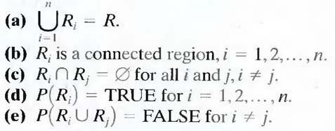
Here, P (Ri) is a logical predicate defined over the points in set Ri and Ǿ` is the null set. Condition (a) indicates that the segmentation must be complete; that is, every pixel must be in a region. Condition (b) requires that points in a region must be connected in some predefined sense. Condition (c) indicates that the regions must be disjoint. Condition (d) deals with the properties that must be satisfied by the pixels in a segmented region—for example P (Ri) = TRUE if all pixels in Ri, have the same gray level. Finally, condition (c) indicates that regions Ri and Rj are different in the sense of predicate P.
Region Growing:
As its name implies, region growing is a procedure that groups pixels or subregions into larger regions based on predefined criteria. The basic approach is to start with a set of "seed" points and from these grow regions by appending to each seed those neighboring pixels that have properties similar to the seed (such as specific ranges of gray level or color). When a priori information is not available, the procedure is to compute at every pixel the same set of properties that ultimately will be used to assign pixels to regions during the growing process. If the result of these computations shows clusters of values, the pixels whose properties place them near the centroid of these clusters can be used as seeds.
The selection of similarity criteria depends not only on the problem under consideration, but also on the type of image data available. For example, the analysis of land-use satellite imagery depends heavily on the use of color. This problem would be significantly more difficult, or even impossible, to handle without the inherent information available in color images. When the images are monochrome, region analysis must be carried out with a set of descriptors based on gray levels and spatial properties (such as moments or texture).
Basically, growing a region should stop when no more pixels satisfy the criteria for inclusion in that region. Criteria such as gray level, texture, and color, are local in nature and do not take into account the "history" of region growth. Additional criteria that increase the power of a region- growing algorithm utilize the concept of size, likeness between a candidate pixel and the pixels grown so far (such as a comparison of the gray level of a candidate and the average gray level of the grown region), and the shape of the region being grown. The use of these types of descriptors is based on the assumption that a model of expected results is at least partially available.
Figure 7.1 (a) shows an X-ray image of a weld (the horizontal dark region) containing several cracks and porosities (the bright, white streaks running horizontally through the middle of the image). We wish to use region growing to segment the regions of the weld failures. These segmented features could be used for inspection, for inclusion in a database of historical studies, for controlling an automated welding system, and for other numerous applications.
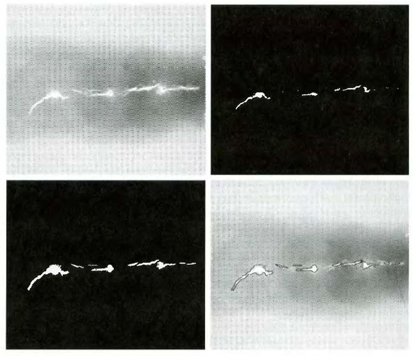
Fig.7.1 (a) Image showing defective welds, (b) Seed points, (c) Result of region growing, (d) Boundaries of segmented ; defective welds (in black).
The first order of business is to determine the initial seed points. In this application, it is known that pixels of defective welds tend to have the maximum allowable digital value B55 in this case). Based on this information, we selected as starting points all pixels having values of 255. The points thus extracted from the original image are shown in Fig. 10.40(b). Note that many of the points are clustered into seed regions.
The next step is to choose criteria for region growing. In this particular example we chose two criteria for a pixel to be annexed to a region: (1) The absolute gray-level difference between any pixel and the seed had to be less than 65. This number is based on the histogram shown in Fig. 7.2 and represents the difference between 255 and the location of the first major valley to the left, which is representative of the highest gray level value in the dark weld region. (2) To be included in one of the regions, the pixel had to be 8-connected to at least one pixel in that region.
If a pixel was found to be connected to more than one region, the regions were merged. Figure 7.1 (c) shows the regions that resulted by starting with the seeds in Fig. 7.2 (b) and utilizing the criteria defined in the previous paragraph. Superimposing the boundaries of these regions on the original image [Fig. 7.1(d)] reveals that the region-growing procedure did indeed segment the defective welds with an acceptable degree of accuracy. It is of interest to note that it was not necessary to specify any stopping rules in this case because the criteria for region growing were sufficient to isolate the features of interest.
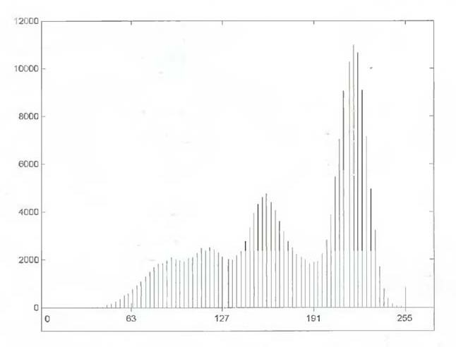
Fig.7.2 Histogram of Fig. 7.1 (a)
Region Splitting and Merging:
The procedure just discussed grows regions from a set of seed points. An alternative is to subdivide an image initially into a set of arbitrary, disjointed regions and then merge and/or split the regions in an attempt to satisfy the conditions. A split and merge algorithm that iteratively works toward satisfying these constraints is developed.
Let R represent the entire image region and select a predicate P. One approach for segmenting R is to subdivide it successively into smaller and smaller quadrant regions so that, for any region Ri, P(Ri) = TRUE. We start with the entire region. If P(R) = FALSE, we divide the image into quadrants. If P is FALSE for any quadrant, we subdivide that quadrant into subquadrants, and so on. This particular splitting technique has a convenient representation in the form of a so-called quadtree (that is, a tree in which nodes have exactly four descendants), as illustrated in Fig. 7.3. Note that the root of the tree corresponds to the entire image and that each node corresponds to a subdivision. In this case, only R4 was subdivided further.
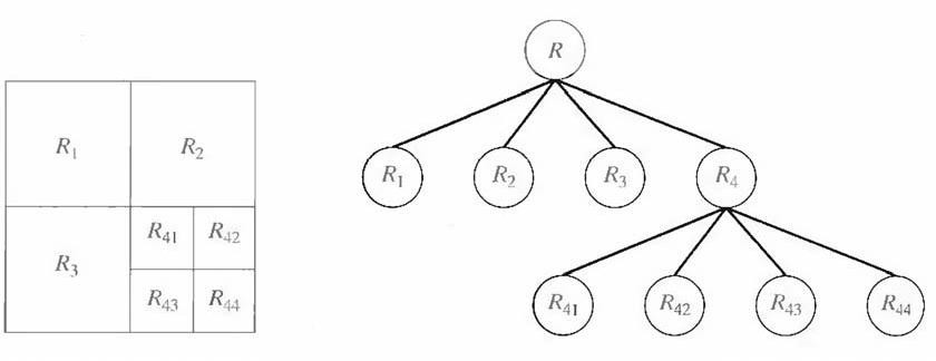
Fig. 7.3 (a) Partitioned image (b) Corresponding quadtree.
If only splitting were used, the final partition likely would contain adjacent regions with identical properties. This drawback may be remedied by allowing merging, as well as splitting. Satisfying the constraints, requires merging only adjacent regions whose combined pixels satisfy the predicate P. That is, two adjacent regions Rj and Rk are merged only if P (Rj U Rk) = TRUE.
The preceding discussion may be summarized by the following procedure, in which, at any step we
- Split into four disjoint quadrants any region Ri, for which P (Ri) =
2. Merge any adjacent regions Rj and Rk for which P (Rj U Rk) =TRUE.
3. Stop when no further merging or splitting is
Several variations of the preceding basic theme are possible. For example, one possibility is to split the image initially into a set of blocks. Further splitting is carried out as described previously, but merging is initially limited to groups of four blocks that are descendants in the quadtree representation and that satisfy the predicate P. When no further mergings of this type are possible, the procedure is terminated by one final merging of regions satisfying step 2. At this point, the merged regions may be of different sizes. The principal advantage of this approach is that it uses the same quadtree for splitting and merging, until the final merging step.